- 您现在的位置:买卖IC网 > Sheet目录507 > SI1141-A10-GM (Silicon Laboratories Inc)IC SENSOR IR PROX/AMBIENT 10-QFN
Si1141/42/43
The window can be applied to either the Visible Ambient Measurement, or the Infrared Ambient Measurement, but
not both. However, monitoring the ambient change in either channel should allow notification that the ambient light
level has changed.
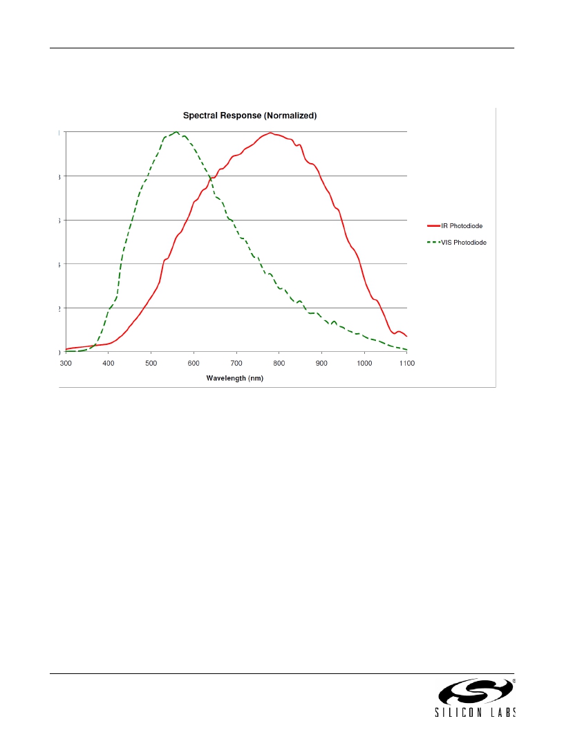
Figure 7. Photodiode Spectral Response to Visible and Infrared Light (Indicative)
2.4. Host Interface
The host interface to the Si1141/42/43 consists of three pins:
?
?
?
SCL
SDA
INT
SCL and SDA are standard open-drain pins as required for I 2 C operation.
The Si1141/42/43 asserts the INT pin to interrupt the host processor. The INT pin is an open-drain output. A pull-up
resistor is needed for proper operation. As an open-drain output, it can be shared with other open-drain interrupt
sources in the system.
For proper operation, the Si1141/42/43 is expected to fully complete its Initialization Mode prior to any activity on
the I 2 C.
The INT, SCL, and SDA pins are designed so that it is possible for the Si1141/42/43 to enter the Off Mode by
software command without interfering with normal operation of other I 2 C devices on the bus.
The Si1141/42/43 I 2 C slave address is 0x5A. The Si1141/42/43 also responds to the global address (0x00) and the
global reset command (0x06). Only 7-bit I 2 C addressing is supported; 10-bit I 2 C addressing is not supported.
Conceptually, the I 2 C interface allows access to the Si1141/42/43 internal registers. Table 15 on page 28 is a
summary of these registers.
An I 2 C write access always begins with a start (or restart) condition. The first byte after the start condition is the I 2 C
address and a read-write bit. The second byte specifies the starting address of the Si1141/42/43 internal register.
Subsequent bytes are written to the Si1141/42/43 internal register sequentially until a stop condition is
14
Rev. 1.3
发布紧急采购,3分钟左右您将得到回复。
相关PDF资料
SI1143-A10-GMR
SENS IR PROXIMITY AMB LT 10QFN
SI1300BDL-T1-GE3
MOSFET N-CH D-S 20V SC-70-3
SI1302DL-T1-GE3
MOSFET N-CH D-S 30V SC-70-3
SI1303DL-T1-GE3
MOSFET P-CH 20V 670MA SOT323-3
SI1305DL-T1-GE3
MOSFET P-CH G-S 8V SC-70-3
SI1307EDL-T1-GE3
MOSFET P-CH G-S 12V SC-70-3
SI1401EDH-T1-GE3
MOSFET P-CH F-D 12V SC-70-6
SI1426DH-T1-GE3
MOSFET N-CH D-S 30V SC-70-6
相关代理商/技术参数
Si1141-A10-GMR
功能描述:近程传感器 I2C Proximity Amb Light Sensor 1 LED RoHS:否 制造商:Vishay Semiconductors 感应方式:Optical 感应距离:1 mm to 200 mm 电源电压:2.5 V to 3.6 V 安装风格:SMD/SMT 输出配置:Digital 最大工作温度:+ 85 C 最小工作温度:- 25 C 系列:VCNL3020
Si1141-A11-GMR
功能描述:近程传感器 I2C Proximity Amb Light Sensor 1 LED RoHS:否 制造商:Vishay Semiconductors 感应方式:Optical 感应距离:1 mm to 200 mm 电源电压:2.5 V to 3.6 V 安装风格:SMD/SMT 输出配置:Digital 最大工作温度:+ 85 C 最小工作温度:- 25 C 系列:VCNL3020
SI1141-A11-YM0R
功能描述:Optical Sensor Ambient 450nm I2C 10-WFQFN 制造商:silicon labs 系列:- 包装:剪切带(CT) 零件状态:有效 类型:环境 波长:450nm 接近探测:是 输出类型:I2C 电压 - 电源:1.71 V ~ 3.6 V 工作温度:-40°C ~ 85°C 安装类型:表面贴装 封装/外壳:10-WFQFN 供应商器件封装:10-QFN(2x2) 标准包装:1
SI1141-M01-GMR
功能描述:Optical Sensor IR 850nm I2C 10-SMD Module (No Lead) 制造商:silicon labs 系列:- 包装:剪切带(CT) 零件状态:有效 类型:IR 波长:850nm 接近探测:是 输出类型:I2C 电压 - 电源:1.71 V ~ 3.6 V 工作温度:-40°C ~ 85°C 安装类型:表面贴装 封装/外壳:10-SMD 模块(无引线) 供应商器件封装:10-QFN(4.9x2.9) 标准包装:1
SI1142
制造商:SILABS 制造商全称:SILABS 功能描述:PROXIMITY/AMBIENT LIGHT SENSOR IC WITH I2C INTERFACE
Si1142-A10-GM
功能描述:近程传感器 IC INTERFACE RoHS:否 制造商:Vishay Semiconductors 感应方式:Optical 感应距离:1 mm to 200 mm 电源电压:2.5 V to 3.6 V 安装风格:SMD/SMT 输出配置:Digital 最大工作温度:+ 85 C 最小工作温度:- 25 C 系列:VCNL3020
Si1142-A10-GMR
功能描述:近程传感器 I2C Prox/Ambient Light Sensor 2LED Dr RoHS:否 制造商:Vishay Semiconductors 感应方式:Optical 感应距离:1 mm to 200 mm 电源电压:2.5 V to 3.6 V 安装风格:SMD/SMT 输出配置:Digital 最大工作温度:+ 85 C 最小工作温度:- 25 C 系列:VCNL3020
Si1142-A11-GMR
功能描述:近程传感器 I2C Proximity Amb Light Sensor 2 LED RoHS:否 制造商:Vishay Semiconductors 感应方式:Optical 感应距离:1 mm to 200 mm 电源电压:2.5 V to 3.6 V 安装风格:SMD/SMT 输出配置:Digital 最大工作温度:+ 85 C 最小工作温度:- 25 C 系列:VCNL3020
